
Description:
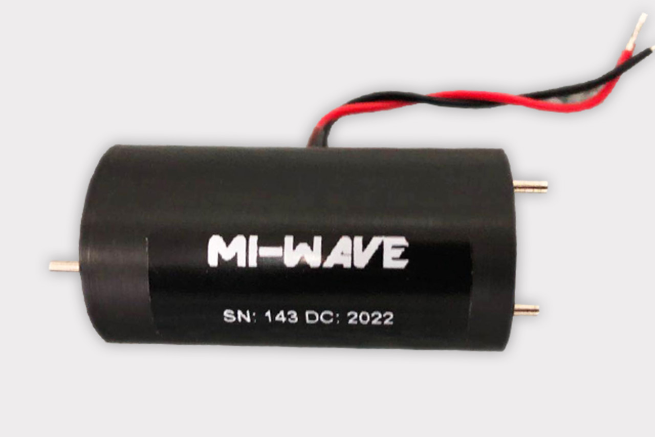
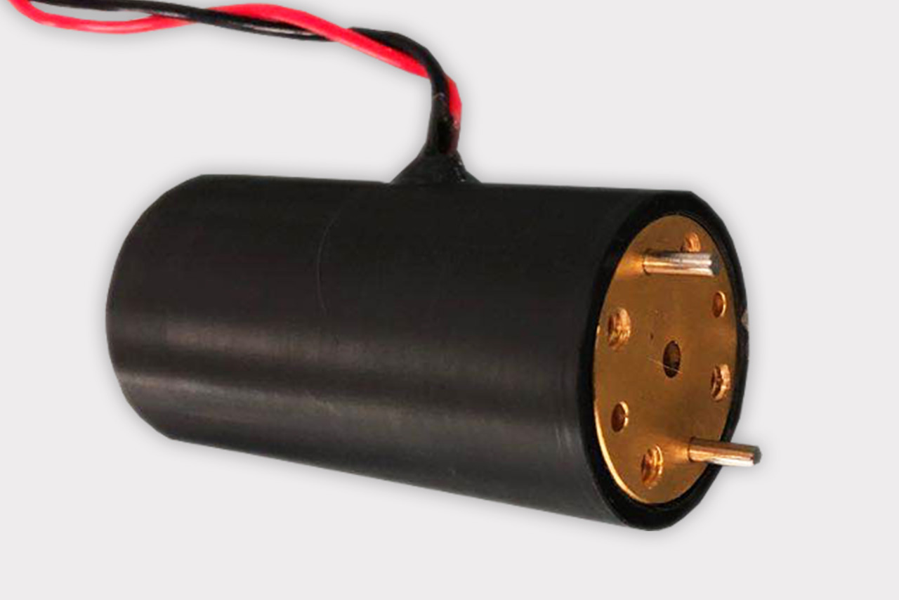
Mi-Wave’s 145 series polarization switch is a TE11 mode device with both the input and output in circular waveguide. It is equipped with a standard pin-aligned circular flange. Typical units are continuously adjustable over ±90° of rotation. Please note that the rotation in Faraday rotators is frequency sensitive. The instantaneous bandwidth of these devices is limited to approximately 1% of the center frequency for a fixed drive current value.
Features
• Low VSWR
• Low Insertion Loss
• Faraday Rotation Devices
• Low Cross-polarization components
Applications
• SatComm
• Test & Measurement Labs
• RF Communication
*Actual product may be different from the image shown per customers specifcations
*All data presented is collected from a sample lot.
* Actual data may vary unit to unit, slightly.
*All testing was performed under +25 °C case temperature.
*Consult factory to confirm if material, plating, size, shape, orientation and any electrical parameter is critical for the application as website information is for reference only.
*Millimeter Wave Products, Inc. reserves the right to change the information presented on website without notice as we continue to enhance the performance and design of our products.
Polarization Switch
Used primarily in conjunction with the antenna product line, the 145 series polarization switch provides a means of remote controlled polarization change. These switches can be used to align polarization between satellite and ground station communication when the satellite polarization is unknown. They are also useful in the test and measurement of circular TE11mode components where axial ratio and ellipticity must be calculated.
Circular waveguide components usually have different frequency bands than the rectangular waveguide components. Therefore, it is usually incorrect to refer to the common rectangular waveguide letter designations when specifying circular waveguide. For the ease of describing electrical specifications, it is convenient to group components in the standard rectangular waveguide frequency bands. Please refer to the circular waveguide chart for actual waveguide sizes. Appendix J