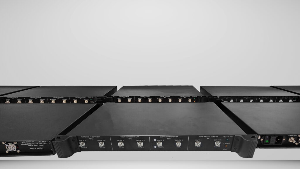
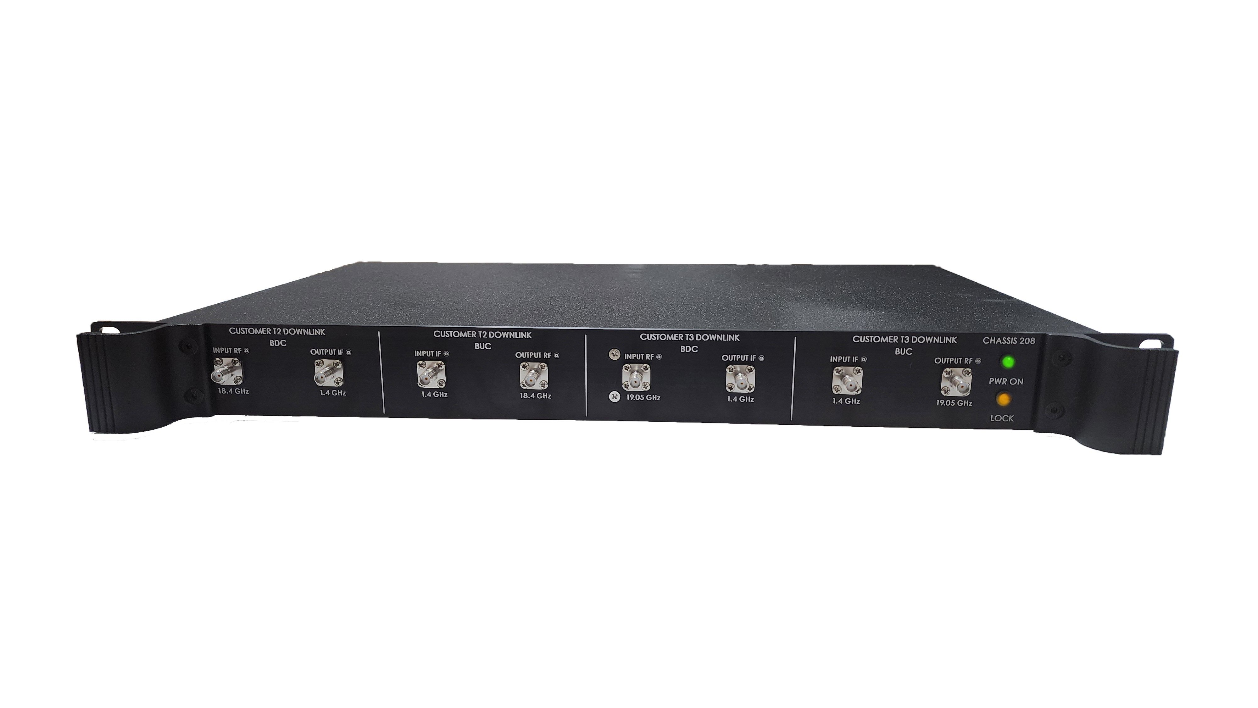
As the global demand for high-capacity satellite connectivity accelerates, Mi-Wave stands at the forefront of innovation in Q-band and V-band systems. From low-noise LNAs and precision up/down converters to high-efficiency BUCs and LNBs, Mi-Wave provides the advanced components and subsystems that power the next generation of satellite uplink and downlink networks. The company designs and manufactures:
- Q-band LNAs with industry-leading low noise figures (< 1.8 dB)
- BUCs, BDCs, LNBs, upconverters, and downconverters optimized for 37.5 – 42.5 GHz and 47.5 – 54 GHz
- Complete Q and V band transmitter and receiver front-ends with high linearity, gain flatness, and temperature stability
- Q and V band Passive and Active components including Antennas https://www.miwv.com/millimeter-wave-products/
Whether you're developing satellite gateways, testbeds, or advanced front-end systems, Mi-Wave provides the engineering depth and manufacturing precision to ensure superior performance at every stage of your uplink and downlink chain.

Why Q- and V-Band Matter for Next-Gen Satellite Systems
As terrestrial and lower-frequency satellite spectrum becomes increasingly congested, satellite operators are turning to the high-capacity feeder-link bands of the microwave / millimeter-wave region. In particular:
- The Q-band (roughly 37.5-42.5 GHz) is being allocated for downlink (space-to-Earth) feeder links.
- The V-band (for example 47.2-51.4 GHz or up to ~54 GHz) is being assigned for uplink (Earth-to-space) feeder links.
- These bands provide wide contiguous bandwidth, enabling higher data-rates and more capacity than legacy Ka/Ku-band feeder links.
- The regulatory environment is evolving to support fixed-satellite-service (FSS) in these bands, with studies and allocations by International Telecommunication Union (ITU-R) and regional bodies.
In practical system terms: you'll see uplink transmitters (Earth station → space) using high-power BUCs (Block Up Converters) in V-band, downlink receivers (space → Earth) featuring downconverters and ultra-low-noise front-ends in Q-band. On the baseband side, the IF signals are processed after the RF frontend (transmitter/receiver chain) and converted to/from the digital domain.
System Architecture: Uplink, Downlink, Transmitter, Receiver, Frontend & Baseband
In a typical gateway or teleport station for an HTS (High Throughput Satellite) or non-GEO system using Q/V-band feeder links, the architecture breaks down as follows:
Transmitter chain (uplink Earth-to-space):
- Baseband: digital data from network/POPs processed (coding, modulation)
- Upconverter/BDC (Block Down/Up Converter): the baseband/IF is upconverted to the V-band RF (e.g., 47.5-54 GHz)
- BUC & high-power PA: boost the RF signal to the required uplink power
- Transmitter frontend: feed to the antenna, often with beam forming, tracking (especially for non-GEO)
Receiver chain (space-to-Earth downlink):
- Receiver frontend: antenna captures the Q-band RF (e.g., 37.5-42.5 GHz)
- Downconverter/LNB: RF is down-converted to IF, often preceded by an LNA (low-noise amplifier) to preserve signal‐to‐noise.
- Baseband: after IF and further conversion, digital processing, demodulation, decoding for data delivery
Because these feeder links operate at high frequencies (EHF), the losses, propagation impairments (e.g., rain-fade) and component performance become critical. For example rain attenuation in Q/V-band can be dramatically higher than in Ka‐band.
Focus: Q-Band LNAs & Low-Noise Front-End Importance
- In the downlink chain (space → Earth) particularly, the first active stage is often a low-noise amplifier (LNA). Why is this so important?


