
Product Description
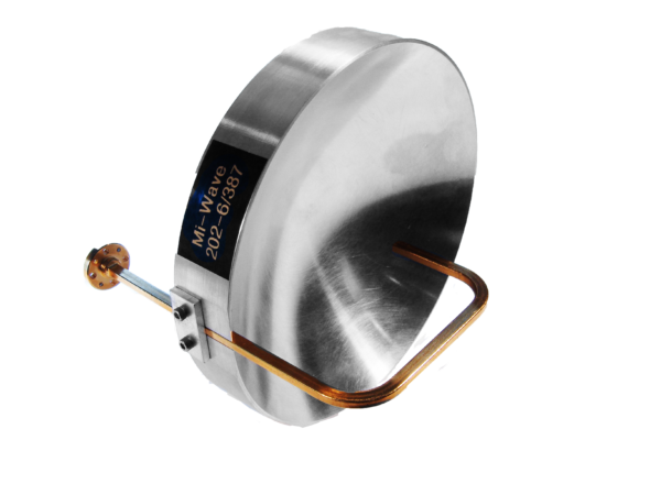
Mi-Wave’s Prime Focus Antennas for Satellite Communications, including the 202 Series (aluminum reflectors) and 203 Series (fiberglass reflectors), are high-gain directional reflector antennas designed to support uplink, downlink, and feeder link operations in modern SatCom systems.
Prime focus antennas use a precision parabolic reflector with a feed positioned at the geometric prime focus of the dish. This configuration delivers narrow beamwidth, high directivity, and symmetrical radiation patterns, making these antennas well suited for satellite gateways, ground stations, and high-capacity point-to-point satellite links.
Mi-Wave prime focus antennas support satellite frequency plans from 8.2 GHz to 110 GHz, including Ka-Band, Q-Band, and V-Band, and are available in multiple reflector sizes to meet specific gain, beamwidth, and installation requirements.
Note: Consult Mi-Wave if material, plating, reflector size, feed configuration, orientation, or electrical parameters are critical to the application. Website information is provided for reference only. The prime focus antennas shown represent only a portion of Mi-Wave’s capabilities. Additional configurations, sizes, and frequency ranges are available upon request.
| Waveguide Band | Model No. | Reflector diameter (inches) | Frequency Range (GHz) | Gain (dB) | 3 dB Beamwidth (degree) | Polarization | VSWR | Antenna Port | Reflector material |
|---|---|---|---|---|---|---|---|---|---|
| X-Band | 202X-18/39 and 203X-18/39 | 18 | 8.2-12.4 | 29 | 4.5 | Linear | 1.3:1 | WR-90 Waveguide with UG-39/U Flange | Aluminum/Fibreglass |
| X-Band | 202X-24/39 and 203X-24/39 | 24 | 8.2-12.4 | 32 | 3.5 | Linear | 1.3:1 | WR-90 Waveguide with UG-39/U Flange | Aluminum/Fibreglass |
| Ku-Band | 202Ku-9/419 | 9 | 12.4-18 | 27 | 5.8 | Linear | 1.3:1 | WR-62 Waveguide with UG-419/U Flange | Aluminum |
| Ku-Band | 202Ku-12/419 and 203-12/419 | 12 | 12.4-18 | 30 | 4.5 | Linear | 1.3:1 | WR-62 Waveguide with UG-419/U Flange | Aluminum/Fibreglass |
| Ku-Band | 202Ku-18/419 and 203-18/419 | 18 | 12.4-18 | 33 | 3 | Linear | 1.3:1 | WR-62 Waveguide with UG-419/U Flange | Aluminum/Fibreglass |
| Ku-Band | 202Ku-24/419 and 203-24/419 | 24 | 12.4-18 | 36.5 | 2 | Linear | 1.3:1 | WR-62 Waveguide with UG-419/U Flange | Aluminum/Fibreglass |
| Ku-Band | 203Ku-36/419 | 36 | 12.4-18 | 40.5 | 1.5 | Linear | 1.3:1 | WR-62 Waveguide with UG-419/U Flange | Fibreglass |
| Ku-Band | 203Ku-48/419 | 48 | 12.4-18 | 43 | 1 | Linear | 1.3:1 | WR-62 Waveguide with UG-419/U Flange | Fibreglass |
| K-Band | 202K-6/595 | 6 | 18-26.5 | 26.5 | 6 | Linear | 1.3:1 | WR-42 Waveguide with UG-595/U Flange | Aluminum |
| K-Band | 202K-9/595 | 9 | 18-26.5 | 30 | 4 | Linear | 1.3:1 | WR-42 Waveguide with UG-595/U Flange | Aluminum |
| K-Band | 202K-12/595 and 203K-12/595 | 12 | 18-26.5 | 33 | 3 | Linear | 1.3:1 | WR-42 Waveguide with UG-595/U Flange | Aluminum/Fibreglass |
| K-Band | 202K-18/595 and 203K-18/595 | 18 | 18-26.5 | 36 | 2 | Linear | 1.3:1 | WR-42 Waveguide with UG-595/U Flange | Aluminum/Fibreglass |
| K-Band | 202K-24/595 and 203K-24/595 | 24 | 18-26.5 | 39 | 1.5 | Linear | 1.3:1 | WR-42 Waveguide with UG-595/U Flange | Aluminum/Fibreglass |
| K-Band | 203K-36/595 | 36 | 18-26.5 | 43 | 1 | Linear | 1.3:1 | WR-42 Waveguide with UG-595/U Flange | Fibreglass |
| K-Band | 203K-48/595 | 48 | 18-26.5 | 45.5 | 1 | Linear | 1.3:1 | WR-42 Waveguide with UG-595/U Flange | Fibreglass |
| Ka-Band | 202A-6/599 | 6 | 26.5-40 | 30 | 4.2 | Linear | 1.3:1 | WR-28 Waveguide with UG-599/U Flange | Aluminum |
| Ka-Band | 202A-9/599 | 9 | 26.5-40 | 33 | 3 | Linear | 1.3:1 | WR-28 Waveguide with UG-599/U Flange | Aluminum |
| Ka-Band | 202A-12/599 and 203A-12/599 | 12 | 26.5-40 | 36 | 2 | Linear | 1.3:1 | WR-28 Waveguide with UG-599/U Flange | Aluminum/Fibreglass |
| Ka-Band | 202A-18/599 and 203A-18/599 | 18 | 26.5-40 | 39 | 1.3 | Linear | 1.3:1 | WR-28 Waveguide with UG-599/U Flange | Aluminum/Fibreglass |
| Ka-Band | 202A-24/599 and 203A-24/599 | 24 | 26.5-40 | 42 | 1.5 | Linear | 1.3:1 | WR-28 Waveguide with UG-599/U Flange | Aluminum/Fibreglass |
| Ka-Band | 203A-36/599 | 36 | 26.5-40 | 45.5 | 1 | Linear | 1.3:1 | WR-28 Waveguide with UG-599/U Flange | Fibreglass |
| Ka-Band | 203A-48/599 | 48 | 26.5-40 | 48 | 0.8 | Linear | 1.3:1 | WR-28 Waveguide with UG-599/U Flange | Fibreglass |
| B-Band | 202B-3/383 | 3 | 33-50 | 26 | 6.5 | Linear | 1.3:1 | WR-22 Waveguide with UG-383/U Flange | Aluminum |
| B-Band | 202B-6/383 | 6 | 33-50 | 32 | 3.5 | Linear | 1.3:1 | WR-22 Waveguide with UG-383/U Flange | Aluminum |
| B-Band | 202B-9/383 | 9 | 33-50 | 36 | 2.5 | Linear | 1.3:1 | WR-22 Waveguide with UG-383/U Flange | Aluminum |
| B-Band | 202B-12/383 and 203B-12/383 | 12 | 33-50 | 38.5 | 1.7 | Linear | 1.3:1 | WR-22 Waveguide with UG-383/U Flange | Aluminum/Fibreglass |
| B-Band | 202B-18/383 and 203B-18/383 | 18 | 33-50 | 42 | 1.5 | Linear | 1.3:1 | WR-22 Waveguide with UG-383/U Flange | Aluminum/Fibreglass |
| B-Band | 202B-24/383 and 203B-24/383 | 24 | 33-50 | 44 | 1 | Linear | 1.3:1 | WR-22 Waveguide with UG-383/U Flange | Aluminum/Fibreglass |
| B-Band | 203B-36/383 | 36 | 33-50 | 48 | 0.7 | Linear | 1.3:1 | WR-22 Waveguide with UG-383/U Flange | Fibreglass |
| B-Band | 203B-48/383 | 48 | 33-50 | 50 | 0.5 | Linear | 1.3:1 | WR-22 Waveguide with UG-383/U Flange | Fibreglass |
| U-Band | 202U-3/383 | 3 | 40-60 | 28 | 5.5 | Linear | 1.3:1 | WR-19 Waveguide with UG-383/U-M Flange | Aluminum |
| U-Band | 202U-6/383 | 6 | 40-60 | 34 | 2.8 | Linear | 1.3:1 | WR-19 Waveguide with UG-383/U-M Flange | Aluminum |
| U-Band | 202U-9/383 | 9 | 40-60 | 37.5 | 2 | Linear | 1.3:1 | WR-19 Waveguide with UG-383/U-M Flange | Aluminum |
| U-Band | 202U-12/383 and 203U-12/383 | 12 | 40-60 | 40 | 1.5 | Linear | 1.3:1 | WR-19 Waveguide with UG-383/U-M Flange | Aluminum/Fibreglass |
| U-Band | 202U-18/383 and 203U-18/383 | 18 | 40-60 | 43 | 1 | Linear | 1.3:1 | WR-19 Waveguide with UG-383/U-M Flange | Aluminum/Fibreglass |
| U-Band | 202U-24/383 and 203U-24/383 | 24 | 40-60 | 46 | 0.7 | Linear | 1.3:1 | WR-19 Waveguide with UG-383/U-M Flange | Aluminum/Fibreglass |
| U-Band | 203U-36/383 | 36 | 40-60 | 49.5 | 0.5 | Linear | 1.3:1 | WR-19 Waveguide with UG-383/U-M Flange | Fibreglass |
| U-Band | 203U-48/383 | 48 | 40-60 | 52 | 0.5 | Linear | 1.3:1 | WR-19 Waveguide with UG-383/U-M Flange | Fibreglass |
| V-Band | 202V-3/385 | 3 | 50-75 | 30 | 4.5 | Linear | 1.3:1 | WR-15 Waveguide with UG-385/U Flange | Aluminum |
| V-Band | 202V-6/385 | 6 | 50-75 | 36 | 2.5 | Linear | 1.3:1 | WR-15 Waveguide with UG-385/U Flange | Aluminum |
| V-Band | 202V-9/385 | 9 | 50-75 | 39 | 1.5 | Linear | 1.3:1 | WR-15 Waveguide with UG-385/U Flange | Aluminum |
| V-Band | 202V-12/385 and 203V-12/385 | 12 | 50-75 | 42 | 1.2 | Linear | 1.3:1 | WR-15 Waveguide with UG-385/U Flange | Aluminum/Fibreglass |
| V-Band | 202V-18/385 and 203V-18/385 | 18 | 50-75 | 45 | 0.9 | Linear | 1.3:1 | WR-15 Waveguide with UG-385/U Flange | Aluminum/Fibreglass |
| V-Band | 202V-24/385 and 203V-24/385 | 24 | 50-75 | 48 | 0.6 | Linear | 1.3:1 | WR-15 Waveguide with UG-385/U Flange | Aluminum/Fibreglass |
| V-Band | 203V-36/385 | 36 | 50-75 | 51 | 0.4 | Linear | 1.3:1 | WR-15 Waveguide with UG-385/U Flange | Fibreglass |
| V-Band | 203V-48/385 | 48 | 50-75 | 54 | 0.3 | Linear | 1.3:1 | WR-15 Waveguide with UG-385/U Flange | Fibreglass |
| E-Band | 202E-3/387 | 3 | 60-90 | 31 | 3.5 | Linear | 1.3:1 | WR-12 Waveguide with UG-387/U Flange | Aluminum |
| E-Band | 202E-6/387 | 6 | 60-90 | 37 | 1.8 | Linear | 1.3:1 | WR-12 Waveguide with UG-387/U Flange | Aluminum |
| E-Band | 202E-9/387 | 9 | 60-90 | 41 | 1.2 | Linear | 1.3:1 | WR-12 Waveguide with UG-387/U Flange | Aluminum |
| E-Band | 202E-12/387 and 203E-12/387 | 12 | 60-90 | 43 | 1 | Linear | 1.3:1 | WR-12 Waveguide with UG-387/U Flange | Aluminum/Fibreglass |
| E-Band | 202E-18/387 and 203E-18/387 | 18 | 60-90 | 47 | 0.6 | Linear | 1.3:1 | WR-12 Waveguide with UG-387/U Flange | Aluminum/Fibreglass |
| E-Band | 202E-24/387 and 203E-24/387 | 24 | 60-90 | 49 | 0.5 | Linear | 1.3:1 | WR-12 Waveguide with UG-387/U Flange | Aluminum/Fibreglass |
| E-Band | 203E-36/387 | 36 | 60-90 | 53 | 0.35 | Linear | 1.3:1 | WR-12 Waveguide with UG-387/U Flange | Fibreglass |
| E-Band | 203E-48/387 | 48 | 60-90 | 55.5 | 0.3 | Linear | 1.3:1 | WR-12 Waveguide with UG-387/U Flange | Fibreglass |
| W-Band | 202W-3/387 | 3 | 75-110 | 33 | 2.9 | Linear | 1.3:1 | WR-10 Waveguide with UG-387/U-M Flange | Aluminum |
| W-Band | 202W-6/387 | 6 | 75-110 | 39 | 1.5 | Linear | 1.3:1 | WR-10 Waveguide with UG-387/U-M Flange | Aluminum |
| W-Band | 202W-9/387 | 9 | 75-110 | 43 | 1 | Linear | 1.3:1 | WR-10 Waveguide with UG-387/U-M Flange | Aluminum |
| W-Band | 202W-12/387 and 203W-12/387 | 12 | 75-110 | 45 | 0.8 | Linear | 1.3:1 | WR-10 Waveguide with UG-387/U-M Flange | Aluminum/Fibreglass |
| W-Band | 202W-18/387 and 203W-18/387 | 18 | 75-110 | 49 | 0.5 | Linear | 1.3:1 | WR-10 Waveguide with UG-387/U-M Flange | Aluminum/Fibreglass |
| W-Band | 202W-24/387 and 203W-24/387 | 24 | 75-110 | 51 | 0.4 | Linear | 1.3:1 | WR-10 Waveguide with UG-387/U-M Flange | Aluminum/Fibreglass |
| W-Band | 203W-36/387 | 36 | 75-110 | 55 | 0.25 | Linear | 1.3:1 | WR-10 Waveguide with UG-387/U-M Flange | Fibreglass |
| W-Band | 203W-48/387 | 48 | 75-110 | 57 | 0.18 | Linear | 1.3:1 | WR-10 Waveguide with UG-387/U-M Flange | Fibreglass |
*All data presented is collected from a sample lot.
* Actual data may vary unit to unit, slightly.
*All testing was performed under +25 °C case temperature.
*Consult factory to confirm if material, plating, size, shape, orientation and any electrical parameter is critical for the application as website information is for reference only.
*Millimeter Wave Products, Inc. reserves the right to change the information presented on website without notice as we continue to enhance the performance and design of our products.
The 202 Series Prime Focus Antennas utilize precision aluminum reflectors engineered to deliver excellent electrical performance across millimeter-wave frequencies from 8.2 to 110 GHz. Available in reflector diameters ranging from 3 to 24 inches, this series is recommended for applications where tight surface tolerances are critical to achieving optimal performance. With typical surface accuracy of 0.001 inch RMS, the 202 Series is well suited for high-performance systems requiring precise beam control and maximum efficiency.
For applications requiring larger reflector diameters, the 203 Series Prime Focus Antennas feature metalized fiberglass reflectors designed to maintain reliable performance across the same 8.2 to 110 GHz frequency range. These antennas are available in diameters from 12 to 48 inches and offer typical surface tolerances of 0.0023 inch RMS. The fiberglass construction provides enhanced structural scalability while maintaining the electrical characteristics needed for demanding RF and millimeter-wave applications.
Key Features
-
Mi-Wave 202 Series aluminum prime focus antennas engineered for lightweight, high-precision SatCom installations where tight surface tolerances, mechanical rigidity, and excellent electrical conductivity are required for high-frequency uplink and downlink performance.
-
Mi-Wave 203 Series fiberglass prime focus antennas designed for outdoor and environmentally demanding gateway deployments, offering enhanced durability, corrosion resistance, and structural scalability for larger reflector diameters.
-
High gain with narrow beamwidth and symmetrical radiation patterns, enabling strong link margins, accurate pointing, and predictable performance in satellite gateway and feeder link applications.
-
Moderate sidelobe performance, providing an effective balance between beam control and system complexity while minimizing interference in dense SatCom environments.
-
Stable electrical performance across microwave and millimeter-wave satellite bands, including Ka-, Q-, and V-Band frequencies used in modern SatCom systems.
-
Precision reflector shaping and feed alignment, ensuring repeatable antenna performance, consistent polarization behavior, and reliable operation across the operating frequency range.
-
Multiple reflector sizes and feed configurations available, allowing system designers to optimize gain, beamwidth, and physical integration for specific gateway and ground station requirements.
-
Support for linear and circular polarization options, enabling compatibility with a wide range of SatCom uplink and downlink architectures.
-
Custom SatCom configurations available, including tailored frequency plans, waveguide interfaces, polarization schemes, mounting solutions, and environmental adaptations to meet specific system requirements.
SatCom Applications
-
Satellite Gateway and Ground Station Antennas
Used in fixed and transportable gateway and ground station installations where high gain, narrow beamwidth, and precise pointing accuracy are required to maintain reliable uplink and downlink performance across satellite frequency bands. -
Ka-Band, Q-Band, and V-Band Feeder Links
Supports high-capacity feeder links operating at Ka-, Q-, and V-Band frequencies, enabling increased bandwidth, higher data rates, and efficient spectrum utilization for next-generation satellite networks. -
Point-to-Point Satellite Communication Systems
Ideal for long-distance, line-of-sight satellite communication links that require focused energy delivery, strong link margins, and minimal interference between adjacent systems. -
High-Throughput Satellite (HTS) Infrastructure
Enables high-throughput satellite architectures by providing the high gain and beam control needed to support multi-beam payloads, aggressive frequency reuse, and high-capacity ground infrastructure. -
Telemetry, Tracking, and Command (TT&C) Systems
Used in satellite telemetry, tracking, and command links where stable radiation patterns, consistent polarization, and predictable antenna performance are essential for reliable spacecraft monitoring and control. -
SatCom Test, Measurement, and System Validation Environments
Applied in laboratory and field test setups for antenna characterization, link budget validation, system commissioning, and performance verification of satellite communication hardware.
Why Choose Mi-Wave for SatCom Prime Focus Antennas
Mi-Wave is a trusted manufacturer of microwave and millimeter-wave antenna systems supporting satellite communication networks worldwide. Our 202 and 203 Series Prime Focus Antennas are engineered to meet the performance and reliability requirements of SatCom gateways, feeder links, and ground station infrastructure.
Material Options for SatCom Environments
-
202 Series (Aluminum Reflectors):
Ideal for controlled or fixed installations where lightweight construction, tight surface tolerances, and high electrical conductivity are required for high-frequency SatCom performance. -
203 Series (Fiberglass Reflectors):
Designed for outdoor and harsh environments, offering enhanced durability, corrosion resistance, and structural scalability for larger reflector diameters.
SatCom-Driven Engineering
Each antenna is designed with careful attention to beam symmetry, sidelobe control, polarization stability, and feed alignment, ensuring consistent performance across satellite frequency bands.
Custom SatCom Solutions
Mi-Wave offers custom prime focus antenna configurations for SatCom systems, including:
-
Ka-, Q-, and V-Band frequency plans
-
Specific gain and beamwidth targets
-
WR waveguide interface selection
-
Polarization requirements
-
Mechanical and mounting adaptations for gateway installations
What Prime Focus Antennas Do for SatCom Systems
Prime focus antennas are high-gain directional reflector antennas used in satellite communications (SatCom) to efficiently transmit and receive RF energy between ground-based terminals and orbiting satellites. These antennas concentrate RF energy by reflecting signals from a parabolic dish toward a feed positioned at the geometric prime focus of the reflector.
This antenna architecture produces a narrow beamwidth, high directivity, and symmetrical radiation pattern, making prime focus antennas well suited for long-range satellite uplinks, downlinks, and feeder links where precise beam control and high link margin are required.
In SatCom systems operating at microwave and millimeter-wave frequencies, prime focus antennas are used to maximize aperture efficiency and improve overall link performance. By focusing electromagnetic energy into a tightly controlled main lobe while minimizing spillover and pattern distortion, these antennas deliver improved gain, pointing accuracy, and repeatable performance, which are critical for gateway terminals, ground stations, and high-throughput satellite networks.
SatCom Frequency Coverage and Waveguide Interfaces
Mi-Wave prime focus antennas support satellite communication frequencies typically ranging from 8.2 GHz to 110 GHz, with extended capability depending on reflector diameter, surface accuracy, and feed configuration. This range supports key SatCom bands used in both legacy and next-generation satellite systems.
These antennas are compatible with standard rectangular waveguide (WR) interfaces, allowing seamless integration into SatCom RF chains, including high-power amplifiers, LNAs, up-converters, down-converters, and monitoring equipment. Supported waveguide sizes and bands include:
-
WR-90 | 8.2–12.4 GHz | X-Band
-
WR-62 | 12.4–18.0 GHz | Ku-Band
-
WR-42 | 18.0–26.5 GHz | K-Band
-
WR-28 | 26.5–40.0 GHz | Ka-Band
-
WR-22 | 33.0–50.0 GHz | Q-Band
-
WR-15 | 50.0–75.0 GHz | V-Band
-
WR-10 | 75.0–110.0 GHz | W-Band
This broad compatibility enables prime focus antennas to integrate directly into high-frequency SatCom ground infrastructure without additional interface complexity.
Why Prime Focus Matters in Satellite Communications
Because the feed is positioned precisely at the prime focus of the parabolic reflector, this antenna design provides several performance advantages that are especially important in SatCom applications:
-
High gain and narrow beamwidth to support long-distance satellite uplink and downlink paths
-
Symmetrical radiation patterns for predictable gateway and ground station performance
-
Stable polarization characteristics across Ka-, Q-, and V-Band operating ranges
-
Consistent electrical performance across multiple frequencies and WR waveguide sizes
These characteristics make prime focus antennas a reliable solution for satellite gateway terminals, feeder links, point-to-point satellite communication systems, and SatCom test, measurement, and system validation environments.