
Products> Amplifiers
Millimeter Wave Amplifiers
Millimeter Wave Amplifiers are critical components in high-frequency RF systems where signal integrity, power efficiency, and precision performance are required. Operating in the millimeter wave spectrum, these amplifiers support advanced applications including radar systems, satellite communications, 5G wireless infrastructure, aerospace, and RF test and measurement.
Millimeter Wave Products, Inc. offers a wide range of high-performance mmWave amplifiers, including high power amplifiers, low noise amplifiers (LNAs), and 5G millimeter wave power amplifiers. Our amplifier solutions are engineered to deliver consistent gain, low noise figures, and reliable output power across demanding frequency bands and operating environments.
In addition to standard designs, we work closely with customers to develop custom millimeter wave amplifier solutions tailored to specific frequency ranges, power levels, system integration requirements, and environmental constraints. Whether supporting commercial, research, or defense applications, our amplifiers are designed to meet the technical demands of modern high-frequency systems.
POWER AMPLIFIERS
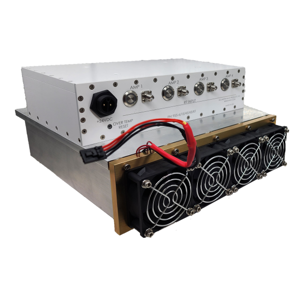
Series 955
LOW NOISE AMPLIFIERS
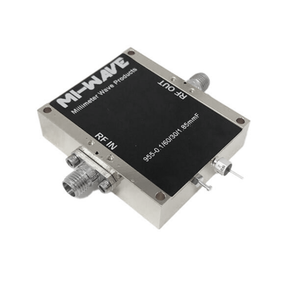
Series 955
5G POWER AMPLIFIERS
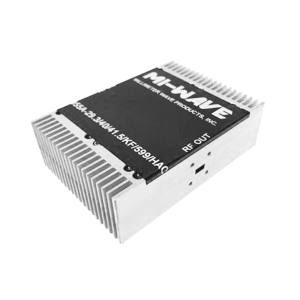
Series 955
Custom Millimeter-Wave Amplifier Design
Millimeter Wave Products provides custom power amplifier and low-noise amplifier (LNA) designs for RF and millimeter-wave systems where off-the-shelf solutions do not meet performance, interface, or environmental requirements.
Custom designs can be optimized for frequency coverage, output power, noise figure, linearity, bandwidth, form factor, and operating conditions across microwave and millimeter-wave bands.
When a Custom Design Makes Sense
A custom amplifier solution is typically considered when one or more of the following apply:
-
Non-standard frequency coverage or wide instantaneous bandwidth
-
Specific output power targets (P1dB or Psat) not available in standard products
-
Tight linearity requirements (OIP3, IM3, ACLR-driven designs)
-
Noise figure optimization for sensitive receiver front ends
-
Mechanical, thermal, or packaging constraints
-
Unique interface requirements (connector type or waveguide flange)
-
Program-specific environmental or reliability requirements
Typical Design Parameters
To evaluate feasibility and scope, the following parameters are commonly defined during the design process:
-
Frequency range / band
-
Target output power (P1dB and/or Psat)
-
Small-signal gain and gain flatness
-
Linearity targets (OIP3, IM3 performance)
-
Noise figure (for LNAs)
-
Bandwidth (instantaneous and operational)
-
Input/output interface (coaxial or waveguide)
-
Bias and power requirements
-
Thermal and environmental considerations
-
Intended application (lab, ground, airborne, or ruggedized)
Design Scope & Deliverables
Depending on program needs, custom amplifier development may include:
-
Circuit design and simulation
-
Device selection and bias optimization
-
Mechanical and thermal considerations
-
Prototype build and RF characterization
-
Test data including gain, output power, linearity, and noise performance
Designs may be delivered as compact modules suitable for system integration or as laboratory-grade assemblies for validation and test environments.
Applications Supported
Custom millimeter-wave amplifier designs are commonly developed for:
-
Defense and aerospace RF systems
-
Radar and sensing platforms
-
Satellite communications and ground terminals
-
5G / FR2 mmWave radio architectures
-
Test and measurement instrumentation
-
Research and prototype development
Working With Us
If you are exploring a custom millimeter-wave amplifier solution, providing preliminary requirements early helps streamline evaluation and design alignment. Both standard amplifier platforms and fully custom designs are supported.
Amplifier Calculators (PA, LNA, and 5G/mmWave)
These calculators support PA output planning, compression headroom (P1dB margin), linearity planning (IIP3/OIP3 and IM3 estimates), EIRP estimates, and thermal dissipation approximations for RF, microwave, and millimeter-wave transmit chains. LNA tools include Friis cascaded noise figure, noise temperature conversion, noise floor, and receiver sensitivity. 5G/mmWave tools support FR2 free-space path loss and quick link budget planning, plus a beamforming-level EIRP estimate.
Jump to: PA Calculators · LNA Calculators · 5G/mmWave Calculators
Power Amplifier (PA) Calculators
Output planning, P1dB headroom, IP3 conversion, IM3 estimate, EIRP, thermal dissipation, and dBm ↔ watts conversion.
Pout (dBm) = Pin (dBm) + Gain (dB) − Loss (dB).
P1dB Margin (dB) = P1dB (dBm) − Pout (dBm).
OIP3 = IIP3 + Gain, and IIP3 = OIP3 − Gain.
IM3 (dBc) ≈ 2 × (OIP3 − Pout per tone).
EIRP (dBm) = Pout (dBm) + Antenna Gain (dBi) − Loss (dB).
Pdiss (W) ≈ Pout(W) × (1/η − 1), where η is efficiency (0–1).
Convert between dBm and watts.
Low Noise Amplifier (LNA) Calculators
Friis cascaded noise figure, noise temperature conversion, noise floor estimation, and receiver sensitivity estimates.
Up to 3 stages. If Stage 3 is unused, leave NF3 and G3 blank.
Assumes T0 = 290 K. T = (F − 1)T0 where F = 10^(NF/10).
Noise Floor (dBm) = N0 + 10·log10(BW) + NF. Default N0 = -174 dBm/Hz.
Sensitivity (dBm) = Noise Floor + Required SNR + Implementation Margin.
5G/mmWave Calculators
FR2 free-space path loss and quick link budget planning, plus a beamforming-style EIRP estimate.
FSPL (dB) = 92.45 + 20·log10(fGHz) + 20·log10(dkm). Received (dBm) ≈ Tx EIRP − FSPL + Rx Gain − Misc Loss.
Approximation: Array Gain (dB) ≈ 10·log10(N). EIRP ≈ Element Pout (dBm) + 10·log10(N) + Element Ant Gain (dBi) − Loss (dB).
Features
Millimeter Wave Products’ power amplifiers, low-noise amplifiers (LNAs), and 5G/mmWave amplifier solutions are designed to support high-frequency RF systems where performance, stability, and integration flexibility are critical.
Wide Frequency Coverage
Support for microwave and millimeter-wave bands including Ka-, Q-, V-, W-band, and FR2 (26–40 GHz and beyond). Designs are available for narrowband or wide instantaneous bandwidth operation depending on application needs.
High Output Power & Gain
Power amplifier solutions provide controlled output power levels defined by P1dB and Psat targets, with stable small-signal gain and predictable compression behavior for transmit and driver stages.
Low Noise Performance
LNA designs emphasize low noise figure and stable gain to support sensitive receiver front ends, improve system noise floor, and maximize receiver sensitivity in high-frequency systems.
Linearity & Spectral Performance
Amplifiers can be optimized for linear operation, supporting applications with strict spectral requirements. Design considerations include OIP3, IM3 performance, and linear output back-off for multi-tone or wideband signals.
Flexible Interfaces
Available with a range of RF interfaces including coaxial connectors and waveguide flanges appropriate for frequency and power level. Mechanical formats support both laboratory and system-integration use.
Thermal & Power Management
Designs account for heat dissipation and bias stability at high frequencies and power levels. Thermal management approaches are selected based on duty cycle, efficiency, and operating environment.
Customizable Architecture
Standard amplifier platforms can be adapted for specific frequency bands, output levels, bandwidths, or mechanical constraints. Fully custom amplifier designs are available when standard products do not meet requirements.
Test & Integration Ready
Amplifiers are suitable for integration into RF test setups, validation environments, and operational systems, with clearly defined electrical and RF performance characteristics to simplify system-level design.
Applications
Millimeter Wave Products’ power amplifiers, low-noise amplifiers (LNAs), and 5G/mmWave amplifier modules are used in high-frequency RF systems where output power, noise figure, linearity, and stability directly affect system performance, range, and compliance.
Defense & Aerospace
Used in telemetry links, datalinks, electronic warfare test systems, and advanced RF front ends requiring stable biasing, repeatable gain, and operation across wide temperature ranges. Suitable for lab, ground, and ruggedized environments.
Radar & Sensing
Supports FMCW and pulsed radar transmit chains, phased-array validation, and sensing systems where controlled output power (P1dB / Psat), gain flatness, and predictable linearity are required.
Satellite Communications (SatCom)
Applied in Ka-band and higher-frequency uplink power stages, driver amplifiers, and receiver front ends for ground terminals, gateways, and system validation. Power amplifiers support EIRP planning, while LNAs optimize receiver sensitivity.
5G / FR2 mmWave Systems
Designed for 26–40 GHz and higher FR2 architectures including beamforming arrays, small-cell radios, and mmWave test platforms. Solutions can be optimized for linearity (OIP3, ACLR-driven designs), output level planning, and array-level EIRP targets.
Test & Measurement / Research
Used in frequency extension modules, wideband drivers, component characterization, and prototype validation where clean spectra, known gain, and flexible connector or waveguide interfaces simplify integration.
Frequently Asked Questions About Millimeter Wave Amplifiers
Millimeter wave amplifiers are used to increase signal strength in high-frequency RF systems. Common applications include radar systems, satellite communications, 5G wireless infrastructure, aerospace and defense platforms, automotive radar, and RF test and measurement environments.
Millimeter wave amplifiers typically operate within the 30 GHz to 300 GHz frequency range. The exact frequency coverage depends on the amplifier design, semiconductor technology, and intended application.
Power amplifiers increase signal power for transmission, prioritizing output power, efficiency, and linearity. Low noise amplifiers (LNAs) are used in receiver chains and are optimized to amplify weak signals while adding minimal noise.
Yes. Millimeter wave amplifiers are essential components in 5G FR2 systems, supporting high-frequency transmission in base stations, small cells, and wireless backhaul applications where high data rates and low latency are required.
Gain describes how much an amplifier increases signal amplitude, typically expressed in dB. Required gain depends on the RF chain design, link budget, and target output power at the operating frequency.
Noise figure describes how much noise an amplifier adds to a signal. Lower noise figure improves receiver sensitivity, which is especially important in low signal level applications such as satellite and sensing receivers.
P1dB is the output power level where the amplifier gain compresses by 1 dB from its small-signal value. It is a common way to describe usable output power and linear operating range.
Linearity describes how faithfully an amplifier reproduces the input signal without distortion. It is commonly characterized using gain compression (such as P1dB) and intermodulation metrics (such as IP3), depending on modulation and system requirements.
Key considerations include operating frequency range, gain, output power, noise figure, linearity, efficiency, DC power requirements, environmental constraints, connector or waveguide interface, and overall system integration needs.
Many millimeter wave amplifiers are designed to operate in demanding environments, including wide temperature ranges and vibration-prone conditions. Environmental requirements should be reviewed during selection or custom design.
Yes. In addition to standard amplifier products, we offer custom millimeter wave amplifier designs tailored to specific frequency ranges, gain levels, output power requirements, mechanical constraints, and system integration needs.
Helpful details include frequency band, required gain, target output power, linearity requirements, noise figure targets (for LNAs), supply voltage and current limits, package constraints, interface type, operating temperature range, and intended application.
Glossary of RF, Microwave, Millimeter-Wave, and 5G Amplifier Terms
This glossary defines commonly used terms related to RF, microwave, millimeter-wave (mmWave), low noise amplifiers (LNAs), and 5G power amplifiers. It is intended for engineers, system designers, and technical buyers evaluating high-frequency amplifier performance.
Core Amplifier Definitions
RF Power Amplifier (PA)
An active RF device that increases the power level of an input signal to drive an antenna, load, or next system stage. RF power amplifiers are typically the final active component in a transmit chain.
Microwave Power Amplifier
A power amplifier designed to operate at microwave frequencies such as X-, Ku-, Ka-, Q-, V-, and W-band, optimized for high gain, stability, and controlled output power.
Millimeter-Wave Power Amplifier
A power amplifier operating above 30 GHz, commonly used in satellite communications, radar, 5G FR2 systems, automotive radar, and scientific research.
Low Noise Amplifier (LNA)
An amplifier designed to amplify very weak signals while adding minimal noise. LNAs are typically placed at the front of receiver chains to preserve signal-to-noise ratio.
Power, Gain, and Linearity
Small-Signal Gain
The amplification provided by an amplifier when operating below compression, expressed in decibels (dB).
Output Power
The RF power delivered at the amplifier output, typically specified in dBm or watts, driven by link budget and regulatory requirements.
1 dB Compression Point (P1dB)
The output power level where amplifier gain is reduced by 1 dB from its linear value, defining the maximum usable linear output power.
Saturated Output Power (Psat)
The maximum output power achievable when the amplifier is driven into saturation.
Linearity
The ability of an amplifier to reproduce the input signal without distortion, critical for wideband and digitally modulated systems.
Third-Order Intercept Point (IP3 / OIP3)
A measure of amplifier resistance to third-order intermodulation distortion. Higher IP3 values indicate better linearity.
Noise and Spectral Performance
Noise Figure (NF)
A measure of how much noise an amplifier adds to a signal, directly impacting overall system sensitivity.
Receiver Sensitivity
The minimum signal level that a receiver can reliably detect, strongly influenced by LNA noise figure and gain.
Harmonics
Unwanted signals generated at integer multiples of the operating frequency, typically reduced through filtering and circuit design.
Spurious Emissions
Discrete unwanted spectral components caused by nonlinear effects or circuit interactions.
Bandwidth and Frequency Characteristics
Operating Frequency Range
The frequency span over which the amplifier meets its specified performance parameters.
Instantaneous Bandwidth
The frequency range supported at one time without tuning, enabling broadband and multi-carrier operation.
Gain Flatness
The variation in amplifier gain across frequency, affecting signal consistency and system calibration.
Impedance, Matching, and Interfaces
Input Return Loss (S11)
A measure of impedance matching at the amplifier input. Higher return loss indicates better matching.
Output Return Loss (S22)
A measure of impedance matching at the amplifier output, affecting power transfer and load stability.
VSWR (Voltage Standing Wave Ratio)
A ratio describing impedance mismatch between the amplifier and load. Lower VSWR indicates improved efficiency and reliability.
Connector or Waveguide Interface
The RF interface used to connect the amplifier, such as coaxial connectors or waveguide flanges, selected based on frequency and power level.
5G and mmWave System Terms
5G FR2 (Frequency Range 2)
The portion of the 5G spectrum operating at millimeter-wave frequencies, typically above 24 GHz.
Beamforming
A technique that electronically steers RF energy using multiple amplifiers and antenna elements to improve coverage and signal quality in mmWave systems.
Error Vector Magnitude (EVM)
A measure of modulation accuracy in digitally modulated systems such as 5G, influenced by amplifier linearity.
Adjacent Channel Leakage Ratio (ACLR)
A metric describing how much transmitted power leaks into adjacent channels, used to evaluate spectral compliance.
Power, Thermal, and Packaging
DC Power Supply
The electrical input required to operate an amplifier, specified by voltage and current.
Biasing
The method of setting operating voltages and currents for active devices to ensure stable performance.
Thermal Management
The removal of heat generated during operation using conduction cooling, heatsinks, or forced air.
Duty Cycle
The percentage of time an amplifier transmits at a given power level, affecting average power dissipation.
Ruggedized Amplifier
An amplifier designed for harsh environments with extended temperature and mechanical tolerance.
Transmit Chain
The sequence of RF components from signal generation through amplification and transmission.
Reliability and MTBF
Long-term operational stability and mean time between failures, critical for mission-critical systems.
Custom Millimeter Wave Amplifier Design
Every application has unique performance requirements, especially in the millimeter wave spectrum. Our custom millimeter wave amplifier design services are built to meet exact electrical, mechanical, and environmental specifications for demanding RF and microwave systems.
We design and manufacture custom mmWave power amplifiers and low noise amplifiers across Ka-band, Q-band, V-band, E-band, and beyond. Whether you need higher output power, ultra-low noise, specific gain flatness, or tight form-factor constraints, our engineering team works directly with you to develop a solution optimized for your system.
Custom Design Capabilities Include:
-
Frequency coverage tailored to your band of operation
-
Output power, P1dB, and linearity optimization
-
Low noise designs for receiver and front-end applications
-
Waveguide or coaxial interfaces (2.92 mm, 2.4 mm, 1.85 mm, waveguide, etc.)
-
Compact, rugged, or temperature-controlled mechanical designs
-
Prototypes through full production builds
Our custom amplifiers are ideal for 5G and 6G research, satellite communications, radar systems, electronic warfare, test and measurement, and aerospace applications. From concept and simulation to testing and delivery, we provide a collaborative design process to ensure your amplifier meets both performance and schedule requirements.
Contact us to discuss your custom millimeter wave amplifier design needs and let us help you build an amplifier solution that fits your application, not the other way around.