
Products> Antenna Products > Cassegrain Antennas
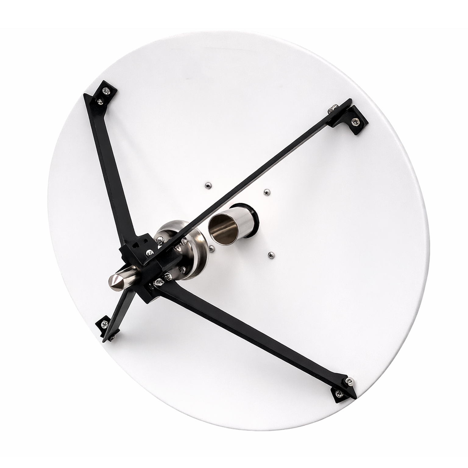
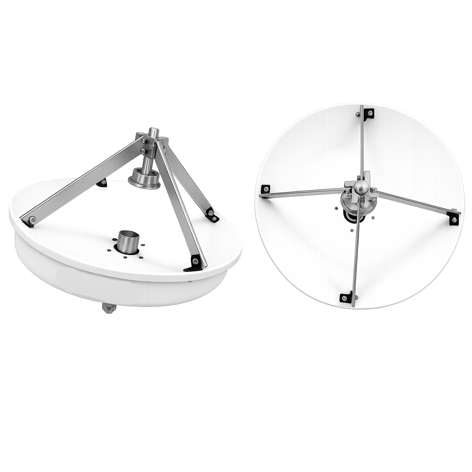
Mi-Wave’s Series 222 and Series 223 Cassegrain reflector antennas are high-performance directional antennas engineered for high gain, narrow beamwidth, and efficient feed integration across RF, microwave, and millimeter-wave frequency ranges. The Cassegrain configuration uses a dual-reflector design, combining a primary parabolic reflector with a secondary hyperbolic sub-reflector to improve feed placement, reduce blockage, and support compact system layouts.
These antennas are well-suited for communications, radar, telemetry, satellite tracking, test ranges, and research systems where precise beam control and repeatable performance matter. Mi-Wave’s current web page lists 5.0 to 110 GHz coverage and 10 to 48 inch diameters, while the legacy Series 223 literature also notes lightweight metallized fiberglass options and extended custom capability beyond the standard range.
- The 222 Series uses aluminum reflector construction,
- The 223 Series uses metallized fiberglass reflectors for lighter-weight antenna structures.
MI-Wave also notes that many additional custom Cassegrain configurations are available beyond the standard models shown online, including variations in diameter, frequency range, polarization, feed arrangement, and mounting.
| Model No. | Waveguide Band | Reflector diameter (inches) | Circular Waveguide Internal Diameter (.XXX in Model No.) in Inches | Frequency Range (GHz) | Gain (dB) | 3 dB Beamwidth (degree) | Polarization | VSWR | Antenna Port | Reflector material |
|---|---|---|---|---|---|---|---|---|---|---|
| 222X-18/.XXX/39 and 223X-18/.XXX/39 | X-band | 18 | .XXX=1.094 .XXX=.938 .XXX= .797 | 8.2-9.97 8.5-11.6 9.97-12.4 | 29 | 4.5 | Circular Polarized | 1.3:1 | Circular Waveguide with UG-39/U Flange | Aluminum/Fibreglass |
| 222X-24/.XXX/39 and 223X-24/.XXX/39 | X-band | 24 | .XXX=1.094 .XXX=.938 .XXX= .797 | 8.2-9.97 8.5-11.6 9.97-12.4 | 32 | 3.5 | Circular Polarized | 1.3:1 | Cicular Waveguide with UG-39/U Flange | Aluminum/Fibreglass |
| 222Ku-18/.XXX/419 and 223-18/.XXX/419 | Ku-Band | 18 | XXX=.660 XXX=.550 | 12.4-14.6 14.6-18 | 33 | 3 | Circular Polarized | 1.3:1 | Circular Waveguide with UG-419/U Flange | Aluminum/Fibreglass |
| 222Ku-24/.XXX/419 and 223-24/.XXX/419 | Ku-Band | 24 | XXX=.660 XXX=.550 | 12.4-14.6 14.6-18 | 36.5 | 2 | Circular Polarized | 1.3:1 | Circular Waveguide with UG-419/U Flange | Aluminum/Fibreglass |
| 223Ku-36/.XXX/419 | Ku-Band | 36 | XXX=.660 XXX=.550 | 12.4-14.6 14.6-18 | 40.5 | 1.5 | Circular Polarized | 1.3:1 | Circular Waveguide with UG-419/U Flange | Fibreglass |
| 223Ku-48/.XXX/419 | Ku-Band | 48 | XXX=.660 XXX=.550 | 12.4-14.6 14.6-18 | 43 | 1 | Circular Polarized | 1.3:1 | Circular Waveguide with UG-419/U Flange | Fibreglass |
| 222K-18/.XXX/595 and 223K-18/.XXX/595 | K-Band | 18 | XXX=.470 XXX .396 XXX=.328 | 18-20.5 20.4-24.5 24.5-26.5 | 36 | 2 | Circular Polarized | 1.3:1 | Circular Waveguide with UG-595/U Flange or UG-425/U Flange | Aluminum/Fibreglass |
| 222K-24/.XXX/595 and 223K-24/.XXX/595 | K-Band | 24 | XXX=.470 XXX .396 XXX=.328 | 18-20.5 20.4-24.5 24.5-26.5 | 39 | 1.5 | Circular Polarized | 1.3:1 | Circular Waveguide with UG-595/U Flange or UG-425/U Flange | Aluminum/Fibreglass |
| 223K-36/.XXX/595 | K-Band | 36 | XXX=.470 XXX .396 XXX=.328 | 18-20.5 20.4-24.5 24.5-26.5 | 43 | 1 | Circular Polarized | 1.3:1 | Circular Waveguide with UG-595/U Flange or UG-425/U Flange | Fibreglass |
| 223K-48/.XXX/595 | K-Band | 48 | XXX=.470 XXX .396 XXX=.328 | 18-20.5 20.4-24.5 24.5-26.5 | 45.5 | 1 | Circular Polarized | 1.3:1 | Circular Waveguide with UG-595/U Flange or UG-425/U Flange | Fibreglass |
| 222A-18/.XXX/599 and 223A-18/.XXX/599 | Ka-Band | 18 | XXX=.328 XXX=.281 XXX=.250 XXX= .219 | 26.5-28.5 28.5-33.0 33.0 -38.5 38.5-40.0 | 39 | 1.3 | Circular Polarized | 1.3:1 | Circular Waveguide with UG-599/U Flange or UG-381/U Flange | Aluminum/Fibreglass |
| 222A-24/.XXX/599 and 223A-24/.XXX/599 | Ka-Band | 24 | XXX=.328 XXX=.281 XXX=.250 XXX= .219 | 26.5-28.5 28.5-33.0 33.0 -38.5 38.5-40.0 | 42 | 1.5 | Circular Polarized | 1.3:1 | Circular Waveguide with UG-599/U Flange or UG-381/U | Aluminum/Fibreglass |
| 223A-36/.XXX/599 | Ka-Band | 36 | XXX=.328 XXX=.281 XXX=.250 XXX= .219 | 26.5-28.5 28.5-33.0 33.0 -38.5 38.5-40.0 | 45.5 | 1 | Circular Polarized | 1.3:1 | Circular Waveguide with UG-599/U Flange or UG-381/U | Fibreglass |
| 223A-48/.XXX/599 | Ka-Band | 48 | XXX=.328 XXX=.281 XXX=.250 XXX= .219 | 26.5-28.5 28.5-33.0 33.0 -38.5 38.5-40.0 | 48 | 0.8 | Circular Polarized | 1.3:1 | Circular Waveguide with UG-599/U Flange or UG-381/U | Fibreglass |
| 222B-18/.XXX/383 and 223B-18/.XXX/383 | B-Band | 18 | XXX=.250 XXX=.219 XXX=.188 | 33.0-38.5 38.5-43.0 43.0-50.0 | 42 | 1.5 | Circular Polarized | 1.3:1 | Circular Waveguide with UG-383/U Flange | Aluminum/Fibreglass |
| 222B-24/.XXX/383 and 223B-24/.XXX/383 | B-Band | 24 | XXX=.250 XXX=.219 XXX=.188 | 33.0-38.5 38.5-43.0 43.0-50.0 | 44 | 1 | Circular Polarized | 1.3:1 | Circular Waveguide with UG-383/U Flange | Aluminum/Fibreglass |
| 223B-36/.XXX/383 | B-Band | 36 | XXX=.250 XXX=.219 XXX=.188 | 33.0-38.5 38.5-43.0 43.0-50.0 | 48 | 0.7 | Circular Polarized | 1.3:1 | Circular Waveguide with UG-383/U Flange | Fibreglass |
| 223B-48/.XXX/383 | B-Band | 48 | XXX=.250 XXX=.219 XXX=.188 | 33.0-38.5 38.5-43.0 43.0-50.0 | 50 | 0.5 | Circular Polarized | 1.3:1 | Circular Waveguide with UG-383/U Flange | Fibreglass |
| 222U-18/.XXX/383 and 223U-18/.XXX/383 | U-Band | 18 | XXX=.219 XXX=.188 XXX=.165 XXX=.141 | 38.5-43.0 43.0-50.0 50.0-58.0 58.0-60.0 | 43 | 1 | Circular Polarized | 1.3:1 | Circular Waveguide with UG-383/U-M Flange | Aluminum/Fibreglass |
| 222U-24/.XXX/383 and 223U-24/.XXX/383 | U-Band | 24 | XXX=.219 XXX=.188 XXX=.165 XXX=.141 | 38.5-43.0 43.0-50.0 50.0-58.0 58.0-60.0 | 46 | 0.7 | Circular Polarized | 1.3:1 | Circular Waveguide with UG-383/U-M Flange | Aluminum/Fibreglass |
| 223U-36/.XXX/383 | U-Band | 36 | XXX=.219 XXX=.188 XXX=.165 XXX=.141 | 38.5-43.0 43.0-50.0 50.0-58.0 58.0-60.0 | 49.5 | 0.5 | Circular Polarized | 1.3:1 | Circular Waveguide with UG-383/U-M Flange | Fibreglass |
| 223U-48/.XXX/383 | U-Band | 48 | XXX=.219 XXX=.188 XXX=.165 XXX=.141 | 38.5-43.0 43.0-50.0 50.0-58.0 58.0-60.0 | 52 | 0.5 | Circular Polarized | 1.3:1 | Circular Waveguide with UG-383/U-M Flange | Fibreglass |
| 222V-12/.XXX/385 and 223V-12/.XXX/385 | V-Band | 12 | XXX=.165 XXX=.141 XXX=.125 | 50.0-58.0 58.0-68.0 68.0-75.0 | 42 | 1.2 | Circular Polarized | 1.3:1 | Circular Waveguide with UG-385/U Flange | Aluminum/Fibreglass |
| 222V-18/.XXX/385 and 223V-18/.XXX/385 | V-Band | 18 | XXX=.165 XXX=.141 XXX=.125 | 50.0-58.0 58.0-68.0 68.0-75.0 | 45 | 0.9 | Circular Polarized | 1.3:1 | Circular Waveguide with UG-385/U Flange | Aluminum/Fibreglass |
| 222V-24/.XXX/385 and 223V-24/.XXX/385 | V-Band | 24 | XXX=.165 XXX=.141 XXX=.125 | 50.0-58.0 58.0-68.0 68.0-75.0 | 58 | 0.6 | Circular Polarized | 1.3:1 | Circular Waveguide with UG-385/U Flange | Aluminum/Fibreglass |
| 223V-36/.XXX385 | V-Band | 36 | XXX=.165 XXX=.141 XXX=.125 | 50.0-58.0 58.0-68.0 68.0-75.0 | 51 | 0.4 | Circular Polarized | 1.3:1 | Circular Waveguide with UG-385/U Flange | Fibreglass |
| 223V-48/385 | V-Band | 48 | XXX=.165 XXX=.141 XXX=.125 | 50.0-58.0 58.0-68.0 68.0-75.0 | 54 | 0.3 | Circular Polarized | 1.3:1 | Circular Waveguide with UG-385/U Flange | Fibreglass |
| 222E-12/.XXX/387 and 223E-12/.XXX/387 | E-Band | 12 | XXX=.141 XXX=.125 XXX=.110 XXX=.094 | 60.0-68.0 68.0-77.0 77.0-87.0 87.0-90.0 | 43 | 1 | Circular Polarized | 1.3:1 | Circular Waveguide with UG-387/U Flange | Aluminum/Fibreglass |
| 222E-18/.XXX/387 and 223E-18/.XXX/387 | E-Band | 18 | XXX=.141 XXX=.125 XXX=.110 XXX=.094 | 60.0-68.0 68.0-77.0 77.0-87.0 87.0-90.0 | 47 | 0.6 | Circular Polarized | 1.3:1 | Circular Waveguide with UG-387/U Flange | Aluminum/Fibreglass |
| 222E-24/.XXX/387 and 223E-24/.XXX/387 | E-Band | 24 | XXX=.141 XXX=.125 XXX=.110 XXX=.094 | 60.0-68.0 68.0-77.0 77.0-87.0 87.0-90.0 | 49 | 0.5 | Circular Polarized | 1.3:1 | Circular Waveguide with UG-387/U Flange | Aluminum/Fibreglass |
| 223E-36/.XXX/387 | E-Band | 36 | XXX=.141 XXX=.125 XXX=.110 XXX=.094 | 60.0-68.0 68.0-77.0 77.0-87.0 87.0-90.0 | 56 | 0.35 | Circular Polarized | 1.3:1 | Circular Waveguide with UG-387/U Flange | Fibreglass |
| 223E-48/.XXX/387 | E-Band | 48 | XXX=.141 XXX=.125 XXX=.110 XXX=.094 | 60.0-68.0 68.0-77.0 77.0-87.0 87.0-90.0 | 55.5 | 0.3 | Circular Polarized | 1.3:1 | Circular Waveguide with UG-387/U Flange | Fibreglass |
| 222W-12/.XXX/387 and 223W-12/.XXX/387 | W-Band | 12 | XXX=.125 XXX=.110 XXX=.094 XXX=.082 | 75.0-77.0 77.0-87.0 87.0-100.0 100.0-110.0 | 45 | 0.8 | Circular Polarized | 1.3:1 | Circular Waveguide with UG-387/U-M Flange | Aluminum/Fibreglass |
| 222W-18/.XXX/387 and 223W-18/.XXX/387 | W-Band | 18 | XXX=.125 XXX=.110 XXX=.094 XXX=.082 | 75.0-77.0 77.0-87.0 87.0-100.0 100.0-110.0 | 49 | 0.5 | Circular Polarized | 1.3:1 | Circular Waveguide with UG-387/U-M Flange | Aluminum/Fibreglass |
| 222W-24/.XXX/387 and 203W-24/.XXX/387 | W-Band | 24 | XXX=.125 XXX=.110 XXX=.094 XXX=.082 | 75.0-77.0 77.0-87.0 87.0-100.0 100.0-110.0 | 51 | 0.4 | Circular Polarized | 1.3:1 | Circular Waveguide with UG-387/U-M Flange | Aluminum/Fibreglass |
| 223W-36/.XXX/387 | W-Band | 36 | XXX=.125 XXX=.110 XXX=.094 XXX=.082 | 75.0-77.0 77.0-87.0 87.0-100.0 100.0-110.0 | 55 | 0.25 | Circular Polarized | 1.3:1 | Circular Waveguide with UG-387/U-M Flange | Fibreglass |
| 223W-48/.XXX/387 | W-Band | 48 | XXX=.125 XXX=.110 XXX=.094 XXX=.082 | 75.0-77.0 77.0-87.0 87.0-100.0 100.0-110.0 | 57 | 0.18 | Circular Polarized | 1.3:1 | Circular Waveguide with UG-387/U-M Flange | Fibreglass |
*All data presented is collected from a sample lot.
* Actual data may vary unit to unit, slightly.
*All testing was performed under +25 °C case temperature.
*Consult factory to confirm if material, plating, size, shape, orientation and any electrical parameter is critical for the application as website information is for reference only.
*Millimeter Wave Products, Inc. reserves the right to change the information presented on website without notice as we continue to enhance the performance and design of our products.
Cassegrain Antenna Engineering Calculators
These RF engineering calculators help estimate antenna performance for Cassegrain reflector antennas, including satcom systems, radar platforms, antenna measurement ranges, and millimeter-wave test environments. Use them to calculate antenna gain, beamwidth, reflector diameter required for target gain, effective aperture, free-space path loss, and wavelength across RF, microwave, and millimeter-wave frequencies.
Cassegrain antennas use a dual-reflector design, so efficiency is often slightly higher than prime focus designs. For many systems, a typical starting efficiency range is 0.55 to 0.75.
Antenna Gain Calculator
Antenna Gain (dBi):
Antenna Beamwidth Calculator
Reflector Size Required for Target Gain
Antenna Effective Aperture Calculator
Effective Aperture (m²):
Free Space Path Loss Calculator
RF Wavelength Calculator
Wavelength (mm):
Key Features & Performance Benefits
High Gain Performance
Cassegrain reflector antennas deliver strong directional gain across RF, microwave, and millimeter-wave frequencies. Their dual-reflector geometry helps concentrate energy efficiently, making them well suited for long-range communication links, radar systems, and precision measurement applications.
Narrow Beamwidth
The high directivity of a Cassegrain antenna produces narrow beamwidths for accurate pointing, improved target resolution, and reduced off-axis interference. This is especially valuable in satellite tracking, radar testing, and antenna range environments.
Compact Feed Integration
The Cassegrain design places the feed closer to the main reflector structure, creating a more compact and practical system layout. This configuration simplifies integration of feeds, waveguide components, and RF hardware while supporting high-frequency operation.
Efficient Dual-Reflector Design
By using both a main reflector and a sub-reflector, Cassegrain antennas can improve illumination efficiency and support strong overall aperture performance. This helps maximize gain while maintaining predictable beam characteristics.
Stable Radiation Patterns
Cassegrain antennas are designed to provide repeatable and controlled radiation performance across their intended operating bands. This makes them ideal for applications where beam shape, sidelobe behavior, and measurement consistency are critical.
Broad Frequency Coverage
Available across wide RF, microwave, and millimeter-wave frequency ranges, Cassegrain antennas support applications from lower microwave bands through Ka, Q, V, and W-Band systems. Their versatility makes them suitable for both commercial and defense-related platforms.
Precision Measurement Capability
These antennas are widely used in antenna test ranges, calibration systems, and laboratory environments where accurate gain, beamwidth, and pattern measurements are required. Their predictable directional performance supports reliable RF testing and validation.
Multiple Reflector Construction Options
Cassegrain antennas are available in different reflector materials, including aluminum and lightweight fiberglass configurations, allowing engineers to balance performance, structural requirements, and environmental needs.
Custom Configurations Available
Custom diameters, feeds, frequency ranges, polarization schemes, and mounting arrangements can be developed for specialized applications. This flexibility supports mission-specific requirements in communications, radar, research, and system integration projects.
Well Suited for High-Frequency Systems
Cassegrain reflector antennas perform particularly well in microwave and millimeter-wave environments where compact feed layouts, high gain, and tight beam control are essential. They are a strong fit for advanced satcom, radar, and test systems.
Applications
Mi-Wave Prime Focus Antennas are widely used across RF, microwave, and millimeter-wave systems that require high-gain directional antennas, predictable radiation patterns, and stable performance across wide frequency ranges. Their precision reflector geometry and controlled beam characteristics make them ideal for both communication systems and RF measurement environments.
These antennas support applications in satellite communications, radar systems, antenna measurement ranges, wireless research, and electromagnetic compatibility testing, where accurate signal transmission and reception are essential.
Satellite Communications (SatCom)
Prime focus antennas are commonly used in satellite communication systems for both uplink and downlink operations. Their high gain and narrow beamwidth allow efficient communication with satellites operating in microwave and millimeter-wave frequency bands.
Typical satcom applications include:
-
Satellite ground terminals and gateway stations
-
Experimental satellite communication links
-
Ka-band, Q-band, and V-band research systems
-
Telemetry and satellite tracking systems
-
Antenna testing for satcom payload development
-
RF link experiments and satellite communication demonstrations
These antennas help provide stable beam patterns and high signal gain, improving link reliability and signal quality in satellite communication environments.
Antenna Measurement Ranges
Prime focus antennas are widely used in antenna measurement facilities where accurate radiation pattern characterization and gain measurements are required.
Typical measurement applications include:
-
Antenna gain and pattern measurements
-
Near-field and far-field antenna testing
-
Calibration of RF antennas and measurement equipment
-
Verification of antenna beamwidth and sidelobe levels
-
RF component and subsystem testing
The predictable radiation pattern of prime focus reflectors makes them well suited for precision RF measurement and calibration environments.
Radar Testing and Radar Systems
Prime focus antennas are often integrated into radar research and radar testing platforms where high directivity and stable beam patterns are required.
Common radar applications include:
-
Radar cross-section (RCS) testing
-
Radar signal transmission and reception
-
Radar calibration and system verification
-
FMCW and pulse radar research systems
-
Microwave and millimeter-wave radar experiments
Their high gain and directional characteristics allow radar engineers to control signal illumination and improve measurement accuracy.
RF and Microwave Laboratory Research
Research laboratories and universities frequently use prime focus antennas in RF and microwave experimental systems for signal transmission, propagation studies, and antenna research.
Typical research applications include:
-
Wireless propagation experiments
-
Microwave and millimeter-wave system development
-
RF component characterization
-
Advanced antenna design research
-
Academic and government research projects
These antennas provide a stable and repeatable RF platform for experimental testing and system prototyping.
EMC and RF Test Facilities
Prime focus antennas are also used in electromagnetic compatibility (EMC) testing environments where controlled radiation patterns and directional signal transmission are required.
Common EMC applications include:
-
Radiated emissions testing
-
RF susceptibility testing
-
Controlled RF illumination in test chambers
-
EMC measurement and compliance verification
-
Antenna system validation
Their directional performance allows engineers to focus RF energy toward specific test targets, improving measurement precision.
Frequently Asked Questions (FAQ)
What is a Cassegrain antenna?
A Cassegrain antenna is a dual-reflector antenna that uses a primary parabolic reflector and a secondary sub-reflector to direct RF energy between the feed and the main dish. This design supports high gain, narrow beamwidth, and compact feed placement.
What are the advantages of a Cassegrain antenna?
Cassegrain antennas offer high directional gain, compact feed integration, narrow beamwidth, and efficient reflector illumination. They are often chosen for systems that need strong performance at microwave and millimeter-wave frequencies while keeping the feed arrangement closer to the antenna structure.
What is the difference between a Cassegrain antenna and a prime focus antenna?
A prime focus antenna places the feed directly at the focal point of the main reflector, while a Cassegrain antenna uses a secondary reflector to redirect energy between the feed and the main reflector. Cassegrain designs can offer more compact packaging and improved feed placement, while prime focus designs are simpler.
What frequencies do Cassegrain antennas support?
Cassegrain antennas can support a wide range of RF, microwave, and millimeter-wave frequencies, depending on reflector size, feed design, and surface accuracy. They are commonly used in X, Ku, K, Ka, Q, V, and W-Band systems.
What determines antenna gain in a Cassegrain antenna?
Antenna gain is primarily determined by reflector diameter, operating frequency, aperture efficiency, and feed illumination quality. Larger reflectors and higher frequencies typically produce higher gain and narrower beamwidth.
Why are Cassegrain antennas often used at high frequencies?
Cassegrain antennas are well suited for higher-frequency systems because their design supports tight beam control, efficient feed integration, and compact placement of RF hardware. These benefits are especially useful in microwave and millimeter-wave applications.
What is beamwidth in a Cassegrain antenna?
Beamwidth is the angular width of the main radiation beam. In Cassegrain antennas, beamwidth decreases as reflector diameter increases or wavelength decreases, allowing for highly directional performance.
What is antenna efficiency in a Cassegrain antenna?
Antenna efficiency describes how effectively the antenna converts input RF power into useful radiated or received energy. In Cassegrain systems, efficiency is influenced by reflector illumination, spillover, blockage, alignment, and surface accuracy.
What are Cassegrain antennas used for?
Cassegrain antennas are commonly used in:
- Satellite communications (SatCom)
- Radar systems
- Antenna measurement ranges
- RF and microwave laboratories
- Telemetry and tracking systems
- EMC and RF test environments
- Millimeter-wave research platforms
Are Cassegrain antennas suitable for test and measurement applications?
Yes. Their high gain, stable radiation patterns, and narrow beamwidth make them well suited for antenna testing, calibration, pattern measurement, and high-frequency RF evaluation.
Can Cassegrain antennas be customized?
Yes. Cassegrain antennas can be customized for diameter, frequency range, feed type, polarization, mounting configuration, reflector material, and environmental requirements.
What materials are used in Cassegrain antennas?
Cassegrain antennas are often available in aluminum and fiberglass reflector constructions, depending on system weight, stiffness, environmental exposure, and frequency requirements.
What is a sub-reflector in a Cassegrain antenna?
The sub-reflector is the secondary reflector positioned between the main reflector and the feed. It redirects RF energy so the feed can be placed closer to the rear or center of the antenna structure.
Why is feed placement important in a Cassegrain antenna?
Feed placement affects mechanical packaging, RF performance, integration with waveguide or coax components, and overall system layout. One advantage of the Cassegrain design is that it allows a more compact feed arrangement than many prime focus designs.
Glossary of Cassegrain Antenna Terms
This glossary defines key terminology related to Cassegrain reflector antennas used in RF, microwave, and millimeter-wave systems. These antennas are commonly used in satellite communications, radar, antenna measurement ranges, RF laboratories, telemetry systems, and research environments where high gain, narrow beamwidth, and compact feed integration are important.
Reflector Antenna Fundamentals
Cassegrain Antenna
A dual-reflector antenna design that uses a main parabolic reflector and a secondary sub-reflector to direct RF energy between the feed and the main dish.
Primary Reflector
The main parabolic reflector surface that shapes and directs the antenna’s radiation pattern.
Sub-Reflector
The secondary reflector used to redirect RF energy between the feed and the primary reflector.
Parabolic Reflector
A curved reflector surface shaped to focus electromagnetic energy toward a focal region.
Reflector Diameter
The physical width of the main reflector. Larger diameters generally provide higher gain and narrower beamwidth.
Reflector Aperture
The effective opening area of the reflector that captures or radiates RF energy.
Reflector Surface Accuracy
The degree to which the reflector surface matches the intended geometry. Higher accuracy is especially important at microwave and millimeter-wave frequencies.
Reflector Rim
The outer edge of the reflector that defines its physical boundary.
Feed System Terms
Feed Antenna
The radiating element that launches or receives RF energy within the reflector system.
Feed Placement
The physical location of the feed relative to the reflector system. In a Cassegrain antenna, the feed is positioned so it works through the sub-reflector rather than illuminating only the main reflector directly.
Horn Feed
A horn antenna commonly used as the feed because of its controlled radiation pattern and broadband RF performance.
Feed Illumination Pattern
The distribution of RF energy from the feed across the reflector system.
Edge Taper
The reduction in feed illumination toward the reflector edge to reduce sidelobes and spillover.
Feed Blockage
Loss caused when the feed or support structure blocks part of the reflector aperture.
Spillover
RF energy that misses the intended reflector surfaces and does not contribute to useful radiation.
Feed Support Structure
The mechanical structure that holds the feed and, in some cases, the sub-reflector in the correct position.
Radiation and Performance Terms
Antenna Gain
A measure of how effectively an antenna concentrates RF energy in a given direction relative to an isotropic source.
Directivity
The degree to which radiation is focused in a preferred direction.
Beamwidth
The angular width of the main radiation lobe.
Half-Power Beamwidth (HPBW)
The angle between the points where gain drops by 3 dB from its peak value.
Main Lobe
The region of strongest radiation in the antenna pattern.
Sidelobes
Smaller radiation lobes outside the main beam.
Back Lobe
Radiation directed behind the main reflector, opposite the main beam.
Radiation Pattern
A graphical representation of how RF energy is distributed in space.
Pattern Symmetry
The degree to which the radiation pattern remains balanced across different planes.
Geometry and Alignment Terms
Focal Point
The location where reflected RF energy converges in a reflector antenna system.
Focal Length
The distance between the reflector and the focal region.
F/D Ratio
The ratio of focal length to reflector diameter. This affects feed design, illumination, and overall system geometry.
Antenna Alignment
The process of orienting the antenna toward the intended signal source or target.
Pointing Accuracy
The precision with which the antenna can be directed.
Pointing Loss
Performance degradation caused by misalignment between the antenna beam and the desired target.
Efficiency and Aperture Terms
Antenna Efficiency
The percentage of input RF power that is effectively radiated or received by the antenna.
Aperture Efficiency
The ratio of effective aperture to physical reflector area.
Effective Aperture
The area over which the antenna effectively collects usable RF energy.
Surface Loss
Loss caused by reflector surface imperfections or conductive limitations.
Ohmic Loss
Signal loss caused by electrical resistance in conductive materials.
Illumination Efficiency
A measure of how effectively feed energy is distributed across the reflector aperture.
Blockage Loss
Losses caused by the physical obstruction of the aperture by the feed, sub-reflector, or support structure.
RF Measurement and Testing Terms
Antenna Measurement Range
A facility used to evaluate antenna gain, beamwidth, polarization, pattern shape, and sidelobes.
Near-Field Region
The region close to the antenna where the electromagnetic field structure is complex and not yet fully formed.
Far-Field Region
The region where the radiation pattern stabilizes and electromagnetic waves behave as plane waves.
Compact Antenna Test Range (CATR)
A system that simulates far-field conditions within a confined indoor test space.
Antenna Calibration
The process of verifying antenna performance using known standards or reference measurements.
Reference Antenna
A calibrated antenna used as a measurement baseline.
RF Frequency and Signal Terms
Radio Frequency (RF)
Electromagnetic frequencies used for communications, radar, sensing, and test systems.
Microwave Frequencies
Typically frequencies from 1 GHz to 30 GHz.
Millimeter-Wave (mmWave)
Typically frequencies from 30 GHz to 300 GHz.
Wavelength
The physical distance between repeating peaks of an electromagnetic wave.
Frequency
The number of cycles per second of an electromagnetic wave.
Application Terms
Satellite Communications (SatCom)
Communication systems that use satellites to relay RF signals between locations.
Ground Station Antenna
A high-gain antenna used to communicate with orbiting satellites.
Uplink
Transmission from Earth to a satellite.
Downlink
Transmission from a satellite to Earth.
Radar Antenna
An antenna used to transmit signals and receive reflections for detection, tracking, and measurement.
Radar Cross Section (RCS)
A measure of how detectable an object is by radar.
Tracking Antenna
An antenna system capable of continuously pointing toward a moving satellite, aircraft, or target.
Telemetry
The transmission of measurement or status data from a remote system to a receiving station.
Common Frequency Bands
- L-Band: 1–2 GHz
- S-Band: 2–4 GHz
- C-Band: 4–8 GHz
- X-Band: 8–12 GHz
- Ku-Band: 12–18 GHz
- Ka-Band: 26–40 GHz
- Q-Band: 33–50 GHz
- V-Band: 50–75 GHz
- W-Band: 75–110 GHz
These frequency bands are widely used in satellite communications, radar systems, wireless links, and millimeter-wave research applications.
Outlines & Drawings
Find your band and view outlines, drawings, data & more.
Why Choose Mi-Wave
Mi-Wave is a trusted manufacturer of RF, microwave, and millimeter-wave antennas and components, supporting commercial, government, and research systems worldwide. Our Series 222 and 223 Cassegrain reflector antennas are engineered to deliver high gain, stable radiation patterns, and reliable long-term performance in demanding high-frequency applications.
High-Frequency Engineering Expertise
With decades of experience in microwave and millimeter-wave antenna design, Mi-Wave develops Cassegrain reflector antennas optimized for aperture efficiency, low sidelobe levels, and predictable beam characteristics across wide frequency ranges.
Precision Manufacturing and Quality Control
Each antenna is manufactured using precision machining, controlled composite fabrication, and careful alignment processes to ensure repeatable electrical performance, mechanical stability, and long-term reliability.
Material Options for Application Flexibility
-
Series 222 aluminum reflectors for lightweight, high-precision, and high-conductivity performance
-
Series 223 fiberglass reflectors for enhanced durability, corrosion resistance, and outdoor use
Custom Antenna Solutions
In addition to standard offerings, Mi-Wave provides custom Cassegrain reflector antenna designs tailored to specific frequency bands, reflector diameters, polarization requirements, feed interfaces, and environmental constraints. Our sales engineering team works closely with customers to ensure seamless system integration.
What Cassegrain Reflector Antennas Are and What They Do
Cassegrain reflector antennas are high-gain directional antennas that use a dual-reflector optical geometry to focus RF energy efficiently while allowing the feed to be positioned close to the main reflector surface.
In this configuration:
-
RF energy is radiated from the feed toward a secondary sub-reflector
-
The sub-reflector redirects the energy toward the primary parabolic reflector
-
The primary reflector collimates the energy into a narrow, highly directional beam
This architecture provides excellent gain, reduced feed blockage, and improved mechanical balance compared to prime-focus reflector designs.
How Cassegrain Reflector Antennas Work
RF energy enters the antenna through a waveguide or feed horn mounted near the main reflector. The signal reflects off the secondary hyperbolic sub-reflector, then off the primary parabolic reflector, and is launched into free space as a highly collimated beam.
This dual-reflection process enables:
-
High gain and narrow beamwidth
-
Reduced feed loss and shorter RF paths
-
Improved aperture efficiency
-
Compact feed and electronics integration
-
Stable radiation patterns across frequency
Frequency Coverage, WR Waveguides, and Supported Bands
Mi-Wave Series 222 and Series 223 Cassegrain reflector antennas are designed to support operation across a wide range of RF, microwave, and millimeter-wave frequency bands, depending on reflector diameter, surface accuracy, feed configuration, and material selection.
Typical operating frequency coverage spans from 8.2 GHz through 110 GHz, with extended capability available through custom designs.
Supported Frequency Bands and WR Waveguide Interfaces
-
X-Band
WR-90 | 8.2–12.4 GHz -
Ku-Band
WR-62 | 12.4–18.0 GHz -
K-Band
WR-42 | 18.0–26.5 GHz -
Ka-Band
WR-28 | 26.5–40.0 GHz -
Q-Band
WR-22 | 33.0–50.0 GHz -
V-Band
WR-15 | 50.0–75.0 GHz -
W-Band
WR-10 | 75.0–110.0 GHz
These waveguide interfaces allow seamless integration with feed horns, transmitters, receivers, LNAs, HPAs, frequency converters, and test instrumentation used in high-frequency RF systems.
Material Considerations by Frequency
-
Series 222 (Aluminum Reflectors)
Optimized for high-frequency and millimeter-wave operation, where tight surface tolerances and high electrical conductivity are critical for maintaining gain and pattern integrity. -
Series 223 (Fiberglass Reflectors)
Designed for larger reflector diameters and outdoor deployments, offering excellent performance across microwave and millimeter-wave bands with enhanced environmental durability and corrosion resistance.
Custom Frequency Support
In addition to standard band coverage, Mi-Wave offers custom Cassegrain reflector antenna designs supporting specialized frequency ranges, non-standard WR interfaces, alternative feed geometries, and application-specific performance requirements.
Why Cassegrain Reflectors Matter
Cassegrain reflector antennas are selected when systems require:
-
High gain in a compact mechanical footprint
-
Long-range RF and microwave links
-
Stable beam pointing and repeatability
-
Efficient feed routing and reduced losses
-
Scalability across frequency and reflector size
These advantages make Cassegrain antennas ideal for communications, radar, telemetry, and precision measurement environments.
Features
-
Dual-reflector Cassegrain architecture
-
High gain with narrow beamwidth
-
Excellent aperture efficiency
-
Reduced feed blockage
-
Compact feed and electronics placement
-
Stable radiation patterns
-
Support for multiple frequency bands
-
Precision aluminum (Series 222) or fiberglass (Series 223) reflector options
-
Suitable for laboratory and field environments
-
Custom configurations available
Applications
-
RF, microwave, and millimeter-wave communication systems
-
Long-range point-to-point links
-
Radar and telemetry systems
-
Antenna characterization and measurement
-
Test and validation environments
-
Research and development platforms
-
Fixed and transportable RF systems