

Mi-Wave Leading the Way in Q/V-Band Satellite Technology
As the global demand for high-capacity satellite connectivity accelerates, Mi-Wave stands at the forefront of innovation in Q-band and V-band systems. From low-noise LNAs and precision up/down converters to high-efficiency BUCs and LNBs, Mi-Wave provides the advanced components and subsystems that power the next generation of satellite uplink and downlink networks. The company designs and manufactures:
- Q-band LNAs with industry-leading low noise figures (< 1.8 dB)
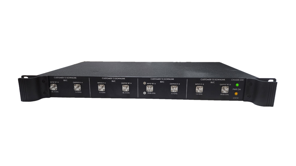
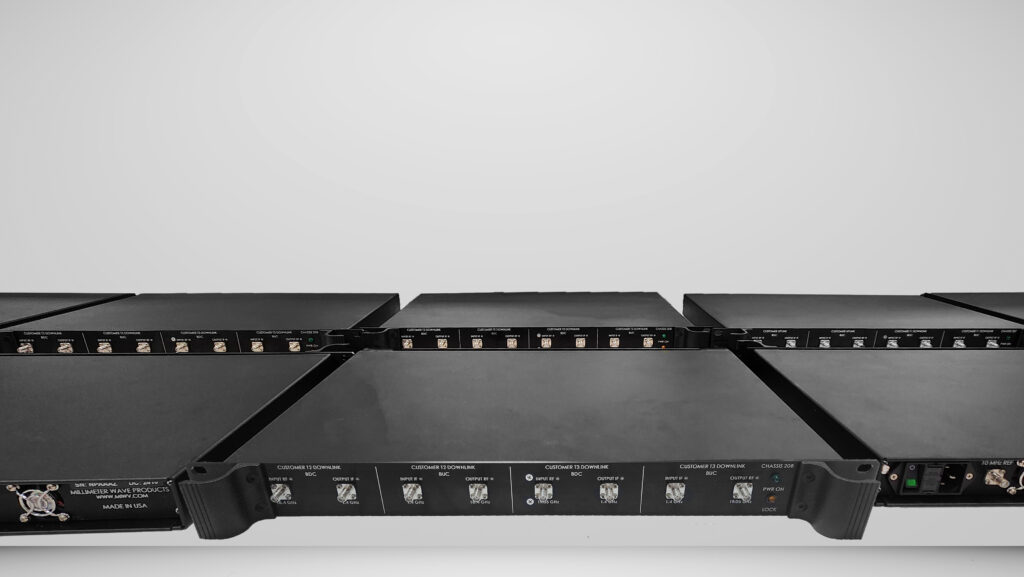
- BUCs, BDCs, LNBs, upconverters, and downconverters optimized for 37.5 – 42.5 GHz and 47.5 – 54 GHz
- Complete Q and V band transmitter and receiver front-ends with high linearity, gain flatness, and temperature stability
- Q and V band Passive and Active components including Antennas https://www.miwv.com/millimeter-wave-products/
Whether you're developing satellite gateways, testbeds, or advanced front-end systems, Mi-Wave provides the engineering depth and manufacturing precision to ensure superior performance at every stage of your uplink and downlink chain.
Why Q- and V-Band Matter for Next-Gen Satellite Systems
- The Q-band (roughly 37.5-42.5 GHz) is being allocated for downlink (space-to-Earth) feeder links.
- The V-band (for example 47.2-51.4 GHz or up to ~54 GHz) is being assigned for uplink (Earth-to-space) feeder links.
- These bands provide wide contiguous bandwidth, enabling higher data-rates and more capacity than legacy Ka/Ku-band feeder links.
- The regulatory environment is evolving to support fixed-satellite-service (FSS) in these bands, with studies and allocations by International Telecommunication Union (ITU-R) and regional bodies.
In practical system terms: you'll see uplink transmitters (Earth station → space) using high-power BUCs (Block Up Converters) in V-band, downlink receivers (space → Earth) featuring downconverters and ultra-low-noise front-ends in Q-band. On the baseband side, the IF signals are processed after the RF frontend (transmitter/receiver chain) and converted to/from the digital domain.
System Architecture: Uplink, Downlink, Transmitter, Receiver, Frontend & Baseband
In a typical gateway or teleport station for an HTS (High Throughput Satellite) or non-GEO system using Q/V-band feeder links, the architecture breaks down as follows:
Transmitter chain (uplink Earth-to-space):
- Baseband: digital data from network/POPs processed (coding, modulation)
- Upconverter/BDC (Block Down/Up Converter): the baseband/IF is upconverted to the V-band RF (e.g., 47.5-54 GHz)
- BUC & high-power PA: boost the RF signal to the required uplink power
- Transmitter frontend: feed to the antenna, often with beam forming, tracking (especially for non-GEO)
Receiver chain (space-to-Earth downlink):
- Receiver frontend: antenna captures the Q-band RF (e.g., 37.5-42.5 GHz)
- Downconverter/LNB: RF is down-converted to IF, often preceded by an LNA (low-noise amplifier) to preserve signal‐to‐noise.
- Baseband: after IF and further conversion, digital processing, demodulation, decoding for data delivery
Because these feeder links operate at high frequencies (EHF), the losses, propagation impairments (e.g., rain-fade) and component performance become critical. For example rain attenuation in Q/V-band can be dramatically higher than in Ka‐band.
Focus: Q-Band LNAs & Low-Noise Front-End Importance
- In the downlink chain (space → Earth) particularly, the first active stage is often a low-noise amplifier (LNA). Why is this so important?
- The LNA sets the noise floor of the entire receiver system. A lower noise figure means better sensitivity and a higher link margin.
- At Q-band (37.5-42.5 GHz) the design of LNAs becomes more challenging: higher frequency means more parasitics, more loss, and higher noise introduced by components.
- As one vendor highlights: a Q-band LNA with an isolator designed for gateway use has a noise figure < 2.5 dB, "excellent signal-to-noise ratios" and "superb gain flatness".
- The isolator ensures better matching to the antenna, reducing losses between the feed and amplifier, improving gain-to-noise-temperature ratio (G/T) and ultimately carrier-to-noise ratio (C/N).
Key takeaways for design and procurement:
- When specifying LNAs for Q-band frontends, look for noise figure (NF) as low as possible (e.g., <2.5 dB or better)
- Ensure good gain flatness across 37.5-42.5 GHz and sufficient input/output matching (VSWR)
- Consider RF chain losses: each dB of loss between antenna feed and LNA degrades system noise figure
- Given high propagation losses and rain fade at EHF, margin is tight — so a high-performance LNA can make the difference between meeting link availability targets or not.
Deployment Considerations & Challenges
Using Q- and V-band feeder links brings tremendous capacity benefits, but also technical and regulatory challenges:
- Propagation & rain-fade: Higher frequencies suffer greater attenuation from rain, atmospheric absorption and scintillation. Measurements show variation up to ~150 dB in extreme conditions at Q/V-band in certain climates.
- Ground-segment hardware: Antennas, converters (upconverter, downconverter, BUC, LNB/BDC) and front-ends must operate reliably at these bands, including thermal stability, precision tracking, beam pointing and calibrations.
- Regulatory / spectrum coordination: The bands (37.5-42.5 GHz downlink, 47.2-50.2 GHz uplink and adjacent ranges) are subject to evolving international regulation and coordination (e.g., European Conference of Postal and Telecommunications Administrations ECC Decision 21(01) for Europe).
- Converter & chain design: Upconverter/downconverter assemblies must preserve signal integrity, low noise, and accommodate wide bandwidth. For example the "TR600 QV-band transceiver" supports 37.5-42.5 GHz and 47.2-52.4 GHz.
The Strategic Opportunity
For broadcasters, enterprise networks, teleports, and even next-gen NTN (Non-Terrestrial Networks) and 5G/6G extensions, Q/V-band feeder links represent a strategic asset:
- They unlock high-capacity feeder links (uplink & downlink) freeing up lower bands for user links.
- They enable gateway architectures that can scale for future satellite constellations (GEO, MEO, LEO) with high throughput.
- When paired with high-performance front-end electronics (especially ultra-low NF LNAs), they elevate the link margin, reliability and service levels.
Summary
In summary, as the satellite industry moves beyond Ka/Ku bands and embraces Q- and V-band feeder links (37.5-42.5 GHz downlink / 47.5–54 GHz uplink), the design of the transmitter/receiver chain, frontend hardware (including upconverter/downconverter, BUC, LNB) and especially the low-noise amplifier (LNA) front-end is critical. Engineers and procurement teams must specify ultra-low noise figure LNAs in the Q-band part of the chain, and ensure high quality converters and robust systems to meet the rigors of EHF propagation, regulatory coordination and system performance demands.
Millimeter Wave Products Inc has built and been part of many special project builds that required upconverters, downconverters, and various components within complex systems. Contact us to discuss your project needs. We can help every step of the way and manufacture your custom parts and RF assemblies with precision and reliability.