Cassegrain Antennas
This guide contains information on a representative group of millimeter wave antennas and feeds that are currently available from Millimeter Wave. The design capability that indicated may also be used to solve other unique requirements in the antenna field. Inquiries outlining special require s for millimeter antennas, antenna feeds and complete antenna systems are cordially invited
Email inquiries to engineering@miwv.com
How To Specify Antennas: Prime Focus Parabolic Antennas
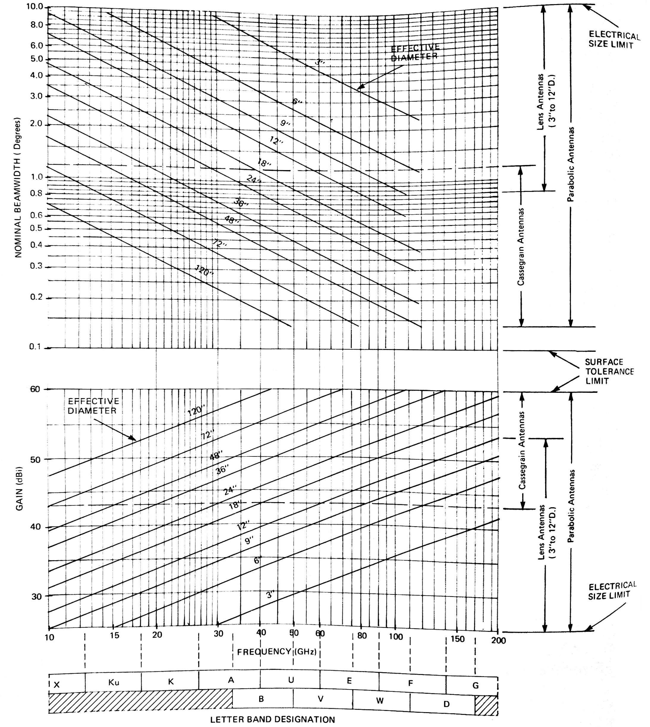
Cassegrain antennas are recommended for frequencies where the feed waveguide attenuation is appreciable and where the reflector is large enough to produce a beamwidth of 1 degree or less. (See Gain/Beamwidth Chart). At millimeter wavelengths, the loss in a waveguide from the input flange to the focus of parabolic reflector can be several dB. This results in a gain loss of the same magnitude. The Cassegrain antenna eliminates most of this loss since the feed horn is placed close to the vertex of the main reflector. The “long run” of waveguide is, therefore, not required and its associated loss is eliminated of this loss since feed horn is pl aced close to the vertex of the main reflector. The “long run” of waveguide is therefore, not required and is associated loss is eliminated.
An additional feature obtainable with the Cassegrain system is lower noise performance. With a standard single-reflector antenna, there is usually considerable energy in wide-angle sidelobes caused by spillover radiation from the small feed. This can introduce a substantial amount of noise power into the antenna by coupling to the radiation pattern from the warm ground. In the case of a Cassegrain antenna, spillover radiation from the virtual feed is usually much less.
Each Cassegrain antenna is composed of a Parabolic main reflector, linearly polarized feed, ( see Note 1 ) subreflector and support assembly. The subreflector support, consisting of four low profile aluminum spars, is attached to the rim of the main reflector to position the subreflector accurately. This spar support present s negligible interaction with the radiated beam.
The 822 Series Cassegrain antenna is constructed with a precision machined aluminum main reflector. This provides optimum performance in the millimeter frequency range of 26.5- to 220 GHz. This precision reflector is especially desirable at frequencies where low surface tolerance (typically 0.001-inch RMS) yields excellent high frequency radiation characteristics. These reflectors are rugged and are used in many heavy duty applications. Tapped mounting holes are provided on each antenna. The standard 822 Series Cassegrain antennas are available with main reflector effective diameters of 12 , 18- and 24-inches. The frequency band range vs. antenna effective diameter available is:
| Band Letter | Series | Diameter (In) |
|---|---|---|
| B,E,K,Ka,Ku,U,V,W,X | 222, 223 | 18 |
| B,E,K,Ka,Ku,U,V,W,X | 222, 223 | 24 |
| B,E,K,Ka,Ku,U,V,W | 223 | 36 |
| B,E,K,Ka,Ku,U,V,W | 223 | 48 |
The 823 Series Cassegrain antennas utilize metallized plastic main reflectors developed with aerospace technology. They offer high performance in a lightweight antenna structure. These antennas are available in effective diameter’s of 18 to 120 inches. Because of the low surface tolerance (typically 0.0025-inch RMS) they provide excellent high frequency radiation characteristic.
The Standard 823 Series Cassegrain antennas are available with main reflector effective diameters of 18-. 24-. 36-. and 48-inches. The Frequency band range vs. antenna effective diameter available is:
| Band Letter | Series | Diameter (In) |
|---|---|---|
| B,E,K,Ka,Ku,U,V,W,X | 222, 223 | 18 |
| B,E,K,Ka,Ku,U,V,W,X | 222, 223 | 24 |
| B,E,K,Ka,Ku,U,V,W | 223 | 36 |
| B,E,K,Ka,Ku,U,V,W | 223 | 48 |
Larger sizes are available and will be quoted upon request
The center frequency should be specified when ordering these antennas. Bandwidths are nominally ± 5 % . Principal plane radiation patterns are supplied with each antenna at the specified design frequency up to 100 GHz.
Beamwidth and Gain Selection Chart